Finally got all the materials I needed to begin building my own miniature muon detector. I swear I had these organized! Unfortunately, some house work caused my neat piles to become a mess. I’ve looked for my soldering iron everywhere in this house but it eludes me. I will keep the building process updated as I go forth. Next challenge: locate the soldering iron and begin the building process.
I’ve completed the build and put it all together – but I get no signal! Not sure what is going on, but I’ll have to double check all solders and builds. There is a set of videos on how to trouble shoot the board – but you need an oscilloscope! I will have to figure out a way to get one-

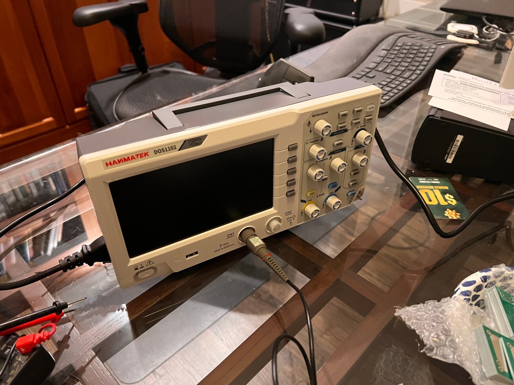
Got an oscilloscope today! A basic, starter one from Amazon. Pretty reasonable, the Hanmatek DoS1102. I have no idea how to use it though, and the manual is not very helpful.
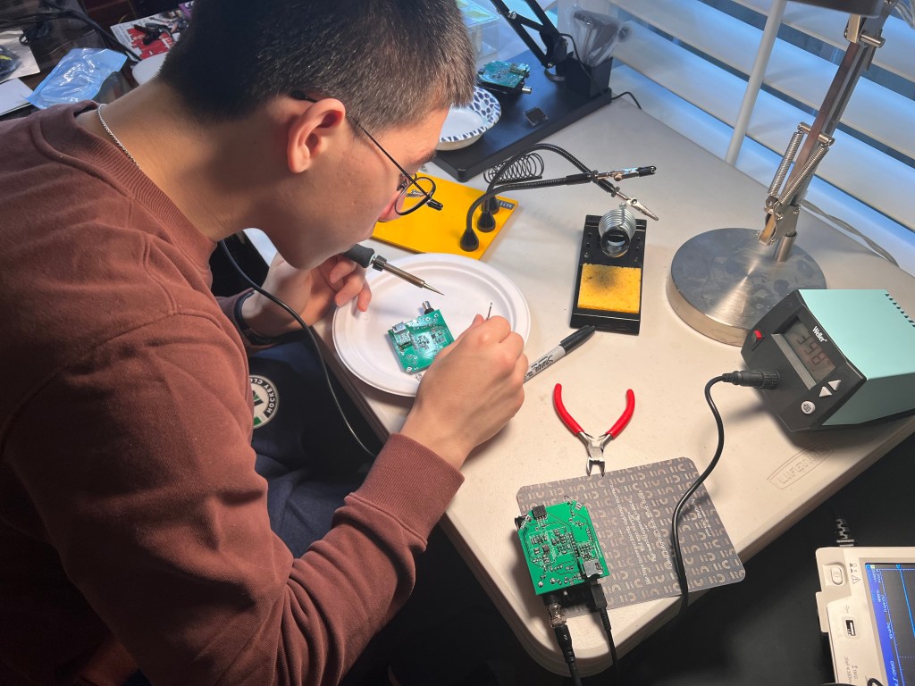
After many, many tries, multiple builds, solders and de-solders, I finally got one working! In hindsight, this all seems so simple and obvious, haha. There is a ton of info from others that have gone through this, including the troubleshooting folder on the CosmicWatch Gitbub as well as various other Reddit conversations, etc. I highly recommend that you look through these, as they were really really helpful.
Once you really get your mind around the circuit board, its really pretty beautiful in how simple it is. Its helpful to keep in mind how it actually works, because it will help you troubleshoot. This is how I think of it:
- Plastic block sees a Muon, emits a photon
- The 29.5V powered SiPM pics up the photon, creates a signal
- Signal is then amplified like 20x so it can be seen
- Tail of the Signal is then reshaped (tail of the signal is made longer) so the Arduino can measure it (otherwise it decays too fast and the Arduino is not fast enough to see it)
- Arduino measures it, displays or records it.
Here is my top learnings from getting this to work!
- Double check all your components are actually correct!
Sometimes, Digikey. Mouser, and other vendors will not have exactly what you order, and offer you an alternative. The alternative may or may not be exactly right. In my case, I thought I ordered the 2.5K ferrite bead as described, but I actually ordered (or they sent to me) a 1k ferrite bead. I didn’t realize this, and when I went back to check, the 2.5K listed on the parts sheet was no longer available from DigiKey, so they sent me a 1K. Now I don’t know if that was going to make a big difference (I believe a ferrite bead is used to smooth power signals), but 2.5 is more than 2x deviation from 1, so I had to go back and correct this on all my boards. I could not find 2.5, so I ordered the 2.7K ferrite bead and that seems to work well for me. - Make sure the plastic scintillator is REALLY REALLY light tight.
OK, this is not to be understated. For the longest time I was getting random insensible readings on my oscilloscope. It took me a while to figure out it was my work lights, my overhead lights, desk lamp, basically any ambient light was bleeding through. Wrap the thing in foil (use the heavy-duty foil, the regular kind will rip too easily). Then wrap it in foil AGAIN. Like a Christmas present. Then wrap it completely in black electrical tape, leaving only the small SiPM window. Then attach the block to the SiPM board with the screws (don’t forget to use optical gel). THEN, you tape it again, taping over all the gaps in the SiPM board to the block, like 2 or 3 times. I criss crossed the black tape. Leave only the leads and support legs sticking out, otherwise it should feel like a completely black box. You would not believe how much light bleeds through from anywhere, including the plastic circuit board itself, if not taped over. If you have any sort of light bleed, it could and most likely will overwhelm the Scintillator so you will not be able to get a clean reading. - Test the voltage across the DC-DC booster circuit
Make sure you read 29.5V, give or take a very small deviation. - Test that the SiPM is acting as it should
Once its installed (pay attention to the orientation of the SiPM!!), use an Ohm meter to test across the 2 connected leads of the SiPM (its easiest to do this from the underside of the circuit board). In one direction, it should read 0. In the other direction, it should read a lot of resistance. - Set up the oscilloscope to read the signal in the right way
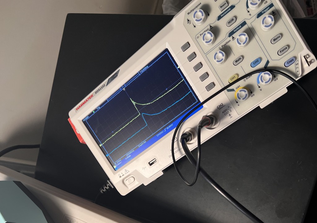
Unless you happen to already know how to use an oscilloscope (I did not), this can be very very confusing. For what its worth, here are some of the settings I used. You may need to play around with yours:
- Probe settings: make sure the 1v/10v is set to 1v, other wise it will think its getting a 10x signal. You can read up on this, but this has to do with common settings on matching oscilloscope to it’s probe. In our case we are using the BNC, so I just set it to 1x.
- Probe is also set to AC coupling (DC coupling is the other option)
- Trigger was set to read Leading Edge (which can sometimes be a picture that looks like _/ ), Normal.
- Make sure to set the trigger voltage to about 30mV
- Acquisition mode was set to “Peak detection
- Test the BNC and TP1
If the scintillator is light tight, the SiPM orientation is correct, the SiPM board (which only has a few components on it) is soldered correctly, and you have 29.5V coming from the DC-DC booster part of the circuit, you should see the nice 100mV periodically, with a 200-300ns decay periodically. TP1 should also see a very similar (but smoother) version of the same signal, since its basically a copy after a 1k resistor. I did NOT initially, which seemed impossible since TP1 is just a straight copy of the BNC signal. Was the resistor broken?! (Unlikely, and easy to test with ohm meter). After days, I figured out I had the 8 pronged LT1807was put in backwards, and I was inadvertently sending a signal the wrong direction. This brings me to #1…check all the components, ESPECIALLY the ones that have a specified orientation!
If you pass this stage, the ‘mechanicals’ of the detector are working! Its seeing Muons, and generating a pulse.
If you are not getting a reading on the Arduino, it’s a soldering or component issue. Double check from both the schematic, the physical board, and parts list to make sure everything is correct.
A really hard thing for me was to solder the tiny legs of the 3 and 4 pronged connectors, and not have them touch / bridge! - Go through TP2 and TP3
Fairly straightforward, but this will tell you if you’re issue is with the amplification part of the circuit, or the peak detection part of the circuit. Spencer Axani’s Youtube video #4 (troubleshooting) explains how to do this pretty well.